A customer asked:
I have a soil plume(apdv) and I have a groundwater plume(aidv).
I really need the spatial intersection of these two. Intersection seems to accommodate serial subsetting where in all of the data is coming from essentially one chemistry file. I have two separate file types I am using.
How do I achieve what I need to do here?
First I want to say that there is a way to do this, but more important, we need to address whether you should do this?
For most sites we want to restrict the estimation of soil data to the vadose zone and groundwater data to the aquifer (saturated zone). Generally the demarcation between these is the water table. When we adhere to our standard practices, there is no overlap of the vadose and saturated zones, therefore any plume within one zone would not intersect a plume in the other zone at all. By Definition.
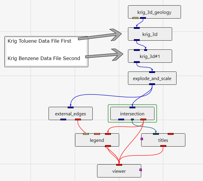
Now, to address the question of how you would determine the intersection of two (or more) analytes that were not specified in the same data file, the process is rather straightforward. The key to making this work is the “Input External Grid” port.
In the application below, the output of krig_3d is passed to the Input External Grid port of krig_3d#1. Each of the kriging modules reads its own unique data file and each can have unique settings, including unique variography settings. Using this methodology, even when different analytes are in the same data file, you can krige each of them with different variograms or other settings by choosing the corresponding “Data Component” within the file.
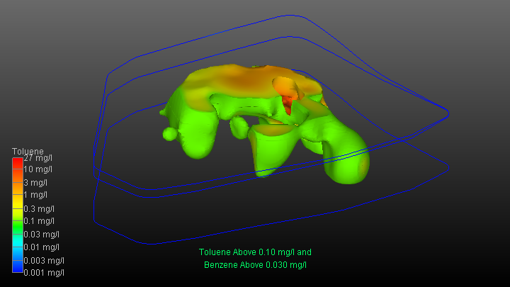
The output this application creates is shown below. Note that when you perform and intersection (or a union) you can only color the plume by one analyte (it doesn’t have to be one of those used in the intersection, but it usually would be). In this case we are coloring by Toluene as shown in the legend.
Finally, I would like to return to the original question regarding the intersection of soil and groundwater plumes. I can see the merit in wanting to know how well the “Bottom” of the soil plume matched the “Top” of the groundwater plume. This exercise really only applies to a relatively new contamination event where one could assume that the soil contamination was the cause of the groundwater contamination.
However, I have personally worked on a great many sites and I cannot recall having the necessary data to make this assessment accurately. I just don’t see deep soil data, right down to the aquifer, and it is even more rare to see multiple screen intervals in Z for the groundwater data that would be needed to properly characterize the vertical distribution of the groundwater contaminant plume. I make this statement in hope that better planning on new projects might result in this type of data being collected.
So, to create this overlapping footprint, you could krige both datasets using the application above, and then surf_cut the result using the water table surface as the cutting surface. With an intersection module you can perform two subsets:
- Below +1.0
- Above -1.0
And it will give you a 2.0 meter (or foot) thick slab centered about the water table. Within that you can look at each of the soil and groundwater plumes and their intersection to assess how well they align.


