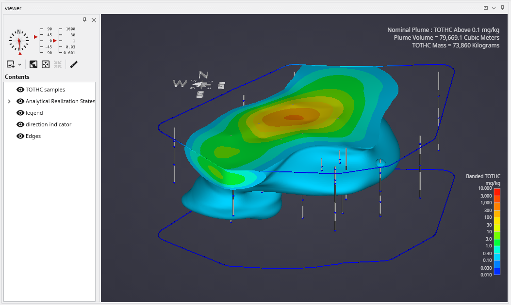
The Viewer is the primary 3D visualization window in Earth Volumetric Studio. It serves as the canvas where all the visual outputs from your Application Network - such as geologic layers, contaminant plumes, sample data, and annotations - are rendered and combined into a single, interactive scene. This is the main environment for exploring, analyzing, and presenting your 3D model.
The Viewer Module and the Application Network
While the Viewer window is where you see your final 3D model, its content is entirely controlled by the viewer module within the Application Network. The viewer module acts as the final destination for all visual elements in your workflow.
Any module that generates a visual object will have a red Renderable Object output port. This port contains all the information needed to draw that object, including its geometry, colors, and rendering properties. See Red Port Properties (Renderable Port).
To display an object, you must connect its red output port to the input port on a viewer module. The Viewer window will then render all the objects it receives from these connections, layering them together to create the final, composite scene. A single application can have multiple viewer modules, each controlling a separate Viewer window with different content.
The Viewer allows you to intuitively navigate and inspect your model from any angle, providing a dynamic way to understand spatial relationships and validate your results.
Basic Mouse Controls
Navigating the 3D scene is done primarily with the mouse. The basic controls are designed to be intuitive for exploring your model.
Action
Mouse Control
Rotate / Tilt
Click and drag with the Left Mouse Button to rotate the view (azimuth) and change the vertical viewing angle (inclination).
Pan
Click and drag with the Right Mouse Button to pan the camera, moving the view horizontally and vertically without changing the rotation.
Zoom
Use the Mouse Wheel to zoom in and out of the scene.
Viewer UI Components
The Viewer window includes a dedicated sidebar on the left that provides access to a variety of tools for controlling the scene and managing its contents. This interface is divided into several key sections.
Component
Overview
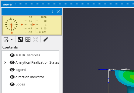
View Orientation Controls
At the top of the sidebar, a compass rose and associated controls allow you to set precise viewing angles or snap to standard orthographic views (e.g., Top, Front, Side). This is essential for creating consistent, reproducible images and analyses.
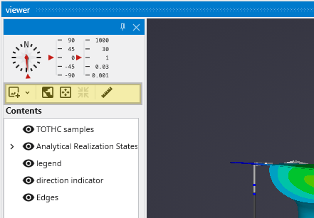
Scene and View Controls
A toolbar below the compass provides buttons for managing the camera and scene. These controls allow you to perform actions like fitting the entire scene into the view, resetting the camera to a default state, and other view manipulations.
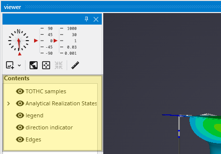
Table of Contents
The lower section of the sidebar contains the Table of Contents, which lists every object currently being displayed in the Viewer. This acts as a layer manager, allowing you to quickly toggle the visibility of individual objects or groups of objects.
The Viewer is the primary 3D visualization window in Earth Volumetric Studio. It includes a dedicated user interface for navigating the 3D scene, managing the visibility of objects, and accessing various tools. Additional, more advanced properties are available in the Properties window when the viewer module is selected.
Subsections of Viewer
The Viewer is the primary 3D visualization window in Earth Volumetric Studio. It includes a dedicated user interface for navigating the 3D scene, managing the visibility of objects, and accessing various tools. Additional, more advanced properties are available in the Properties window when the viewer module is selected.
Viewer Window Interface
The Viewer window features a sidebar on the left that contains controls for orientation, scene management, and a table of contents
View Orientation Controls
At the top of the sidebar, the orientation controls allow for precise camera positioning.
Control
Description
Compass Rose
Provides a visual indicator of the current view orientation (North, South, East, West). You can click and drag the needle on the compass to adjust the camera’s Azimuth (horizontal rotation) or click any of the subdivisions to set the view direction.
Inclination Slider
The vertical slider next to the compass controls the camera’s Inclination (vertical tilt). Drag the indicator up or down to change the viewing angle, from a top-down plan view (90°) to a side profile view (0°) or click any of the subdivisions for pre-set values.
Scene and View Controls Toolbar
A toolbar below the orientation controls provides quick access to common scene management functions.
Button
Icon
Description
Save Viewer Snapshot
Saves the current contents of the viewer to an image file. Clicking the main button saves with the last used settings, while the dropdown arrow reveals several options to control the output:
**Use Transparent Background**: If enabled (and using PNG format), the viewer background will be transparent in the saved image.
**Prefer Lossless**: When enabled, attempts to save in a lossless format like PNG.
**Quality**: Sets the compression quality for lossy formats like JPEG (1-100).
**View Scale**: A multiplier for the output resolution. A scale of 2.0 will produce an image twice the width and height of the current viewer size.
**Scale Forward Facing Text**: Ensures that text elements scale correctly with the View Scale to maintain their relative size.
|
| **Set Top View** |  | Instantly sets the camera to a top-down plan view (90° inclination), looking straight down the Z-axis. |
| **Zoom To Fit** |  | Automatically adjusts the camera's zoom and position to ensure all visible objects in the scene fit perfectly within the viewer window. |
| **Center On Picked Point** |  | Recenters the camera's rotation point around the location most recently "picked" in the viewer. To pick a new point, hold **Ctrl** and left-click on an object in the scene. |
| **Measure Distances** |  | Activates the distance measurement tool. After enabling, you can pick two points in the scene (using **Ctrl+Left Click** for each) to measure the 2D and 3D distance between them. |
Table of Contents
The Contents section at the bottom of the sidebar acts as a layer manager for your scene. It displays a hierarchical tree view of every object connected to the viewer module in the Application Network.
Visibility Control: Each item in the list has an eye icon next to it. Clicking this icon toggles the visibility of that object in the viewer. This allows you to quickly show or hide different components of your model without disconnecting modules. Objects hidden in the Table of Contents will also be hidden in exported C Tech Web Scenes (.ctws).
Tree Structure: If you use modules like group_objects, the Table of Contents will reflect that structure. You can expand or collapse parent items to show or hide their children, and toggling the visibility of a parent will affect all the objects grouped under it.
Double Click Interaction: Double left-click with your mouse on any item in the Table of Contents will select that module in the the-application-window.mdApplication, as well as show it’s properties in the Properties Window.