The write_vrml output in the viewer is able to output most graphics objects in the viewer to a VRML-formatted file.
VRML is a network transparent protocol for communicating 3D graphics. It has fallen out of favor on the web, though it is still a standard for 3D model output.
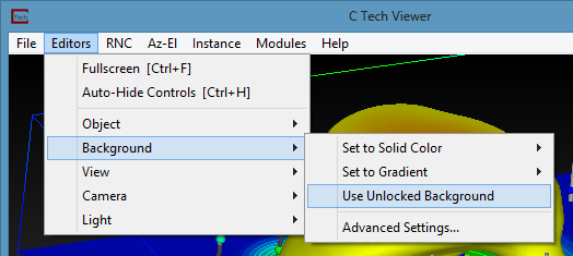
Turn on the “Use Unlocked Background” option in the viewer->Background editor when writing VRML files, since the background is otherwise rendered as a small square at the origin.
Always set your viewer to a Top View (180 Azimuth and 90 Inclination) before writing the VRML file.
Do not use any modules which display in the 2D overlay. The 2D overlay is analogous to drawing on the glass on a TV or monitor. Items in the 2D overlay do not move, rotate or scale when you manipulate your 3D model. Examples are add_logo, Titles, and legend.
Do not use volume rendering. These techniques are not supported.
VRML does not support the full spectrum of data coloring supported in EVS.
Though both cell and nodal data coloring is supported, sometimes combinations of these cause problems.
Object colors (such as the red, blue, green grid lines of the axes module) often revert to white (uncolored). This can be problematic on a white background.
The texture_colors module is recommended for final output of most all colored objects to help avoid these issues.
Trial and Error is often the only way to determine what combinations of rendering modes are supported, especially for 3D PDF and 3D printing. Remember these vendor’s software all interpret the VRML files in slightly different ways. You will likely not be able to do everything you can do in a 4DIM or in EVS.
VRML viewers: There is a list of VRML viewing software published by National Institute of Standards and Technology here. We recommend Cosmo, though it is far from perfect. We have created VRML files which will not display correctly in any of the VRML viewers that we have tested (including Cosmo), but which DO convert to 3D PDF perfectly. Conversely, there are occasions when something will look ok in VRML and not convert properly to 3D PDF.
Guidelines for 3D Printing The following is a list of guidelines that must be considered when making visualizations that will be printed using 3D Systems (previously Zcorp) technology. As of this software release, no other full color 3D printer has been successfully tested with output from write vrml. You must follow the guidelines in write vrml in addition to these additional guidelines.
Subsections of write vrml
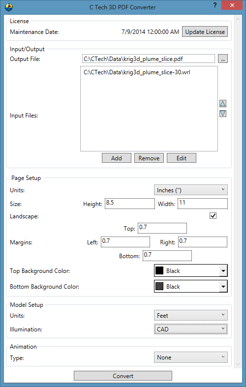
The following is a list of guidelines that must be considered when making EVS models that will be output as 3D PDF files using the C Tech 3D PDF Converter.
Note: The C Tech 3D PDF Converter is a separately purchased product not included with any other C Tech software licenses. Please see www.ctech.com for pricing.
EVS output from write_vrml. You must follow the guidelines in write_vrml in addition to these additional guidelines.
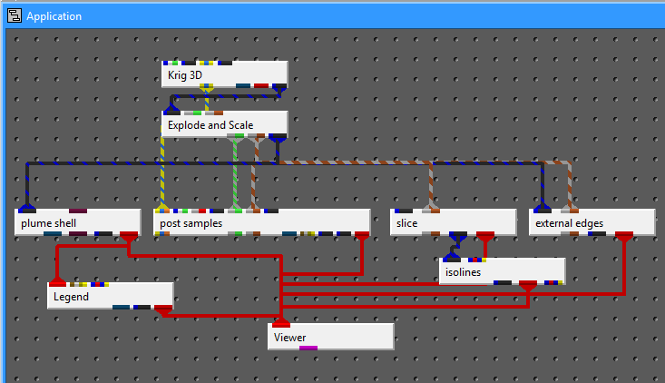
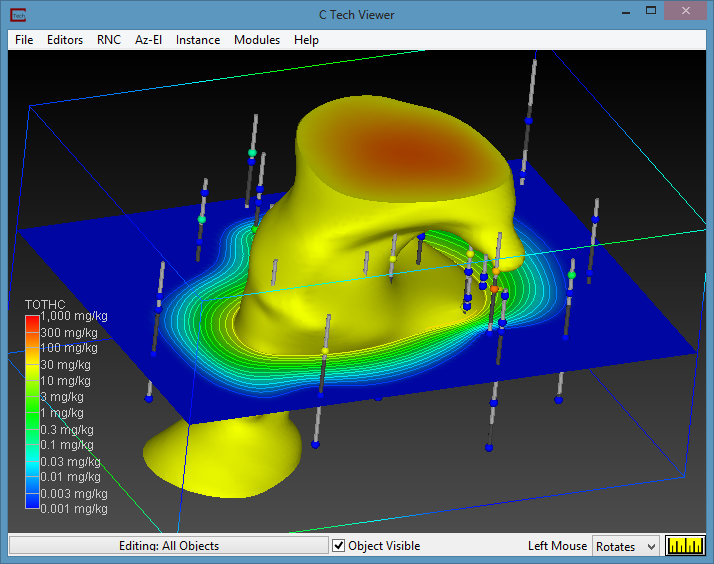
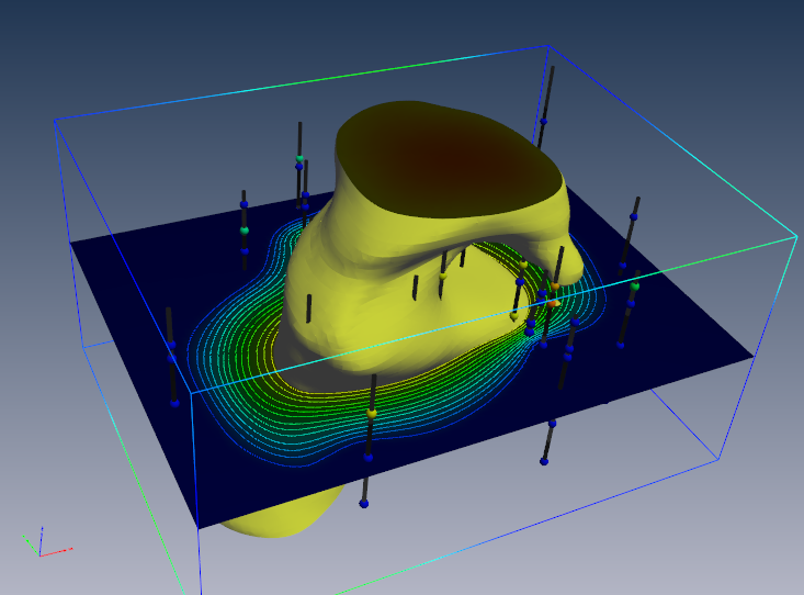
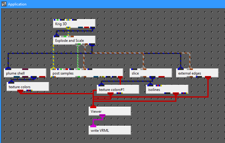
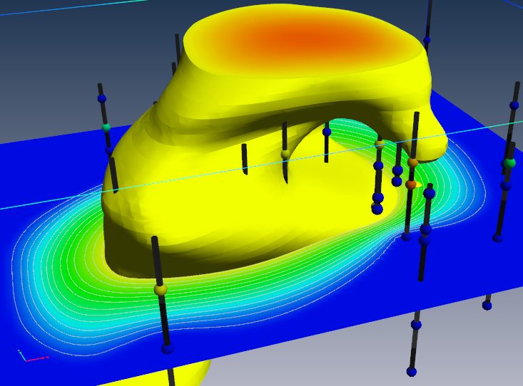
Let’s begin by building a simple application
Whose output is:
The first things we MUST do for VRML output are to remove the legend and use an Unlocked Background. If you see a gradient background in your viewer, you definitely aren’t using an unlocked background. Once you use an unlocked background, you can still set a solid (single) background color.
Always set your viewer to a Top View (180 Azimuth and 90 Inclination) before writing the VRML file.
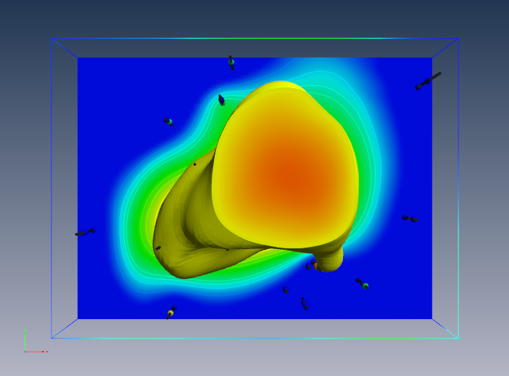
If we output this current model as VRML and convert to 3D PDF,
the results are less than wonderful:
The above 3D PDF has three obvious problems:
The top and bottom of the plume are very dark.
The slice is dark
post_sample’s borings are dark.
We need to modify the application using two texture_colors modules as follows:
You’ll notice that in the revised application, the output in the viewer is virtually identical. This will address the first two problems, however we expect to resolve the dark borings in an upcoming release.
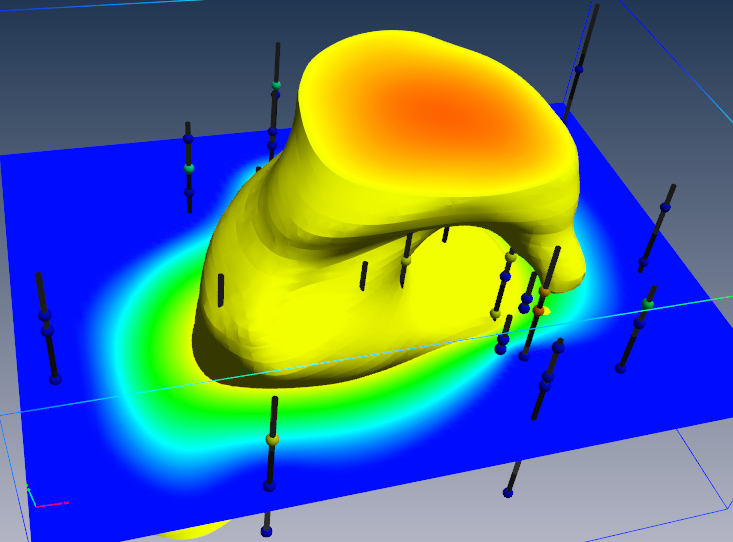
If we export this model to VRML and convert to PDF, the result is:
One other issue is that by default, we create isolines coincident with the surface(s) and resolve the coincidence in EVS using jitter. At some rotations you will notice that the isolines may disappear. This can be because jitter is not supported, but also because the underlying surface is so bright that the lines are not distinguishable.
This can be addressed using the surface_offset parameter in isolines. This will offset the lines from teh surface (in one direction) and eliminate the coincidence. However, this will also mean that the lines will not be visible from one side of the slice. Making the lines uncolored is another option.
Guidelines for 3D Printing
The following is a list of guidelines that must be considered when making visualizations that will be printed using 3D Systems (previously Zcorp) technology. As of this software release, no other full color 3D printer has been successfully tested with output from write vrml. You must follow the guidelines in write vrml in addition to these additional guidelines.
These guidelines are provided to minimize printing problems. Users should fully understand the issues below or they will likely not create VRML files suitable for 3D printing. Given the cost of the raw material it is best to do it right the first time!
Many of these issues (if not heeded) will be obvious when the model is viewed in Z Corp’s ZPrint software. Make sure the model is carefully examined in ZPrint before actual printing.
Internal Faces: You must avoid internal External faces. This naturally occurs when we cut a hexahedral volumetric model with our older plume module. The volumetric subset consists of hexahedron and tetrahedron cells. This creates surfaces that are internal to the model even though they represent the external faces of each set of cells. The real problem here is that the mating surfaces of each cell set are coincident (see 4 below). This major problem and many others are resolved by the intersection shell module.
Normals: Must have all surface normals facing outward to define a solid volume for printing (handled by intersection shell module)
Coincident surfaces: You CANNOT HAVE coincident surfaces. If two layers (or other objects) have coincident surfaces this will result in open parts and printing problems. You must separate the parts by a small amount (recommend 0.005 inches in final printed size) which should not be noticeable visually. Z-Print’s process will fuse these parts together (because there isn’t sufficient gap to keep them truly separate).
Overlapping parts: This is supported. It is possible to have two closed volumes overlap each other and Z-Print will sort it out so long as 1, 2 and 3 above are still valid.
Surfaces: Must be extruded or represented as a volumetric layer. Surfaces have no thickness and if placed coincident with the top of a volumetric object will result in leaving the volume OPEN (unclosed). This will cause serious problems.
Cell Data: Another limitation is the inability to mix nodal and cell data. Since we use nodal data for so many things you should always strip out the cell data and use nodal data exclusively. You must be aware of the following:
Ensure that there are no modules connected to the viewer that contain cell data. The safest way to ensure this is to pass questionable modules through extract_mesh with “Remove Cell Data” toggle ON. Normally you would want the “Remove Nodal Data” toggle OFF.
If you want your cell data (colors) to be displayed, pass the cell data through the cell data to node data module. However be aware that you’ll still need to use extract_mesh afterwards because cell data to node data doesn’t remove the cell_data it just creates new nodal data from cell data.
Typical modules that have cell data are import vector gis, lithologic modeling, Solid_3D_Set, Solid_contour_set, and most of the modules in the Cell Data library.
Explode distance: Need to ensure that there is sufficient gap between exploded layers (separate parts) so that they don’t fuse together. Separation should be 1 mm (0.04 inches) minimum in the final print scale. Be aware that a 1 mm gap in the Z direction isn’t equivalent to a 1 mm separation if the mating parts have high slopes. If your mating surfaces have a 45 degree slope, the separation is reduced by cos(45) (~0.7). If you have higher slopes such as 80 degrees, the factor would be ~0.17. This would mean that you would need a Z gap of nearly 6 mm to ensure a 1 mm separation between parts.
Disconnected pieces: Although Z Print can print disconnected pieces, they won’t retain their spatial position. Plumes that aren’t connected to solid structure will just be loose pieces in the final print. This would also apply to post samples’ borings and spheres, unless they are connected by some common surface or geologic layer.
Concepts that are NOT Supported:
Points and Lines: Points and Lines cannot be printed (except as elements of an image used in a texture map). Lines must be converted to some 3D solid structure (such as closed tubes) and they must be of sufficient thickness to have some strength AND must not be disconnected pieces. Points should be represented as glyphs of sufficient size and not be disconnected.
Transparency: Transparency as an object property cannot be supported since Z Print’s ink is printed onto opaque plaster or starch powder. The illusion of transparency could be achieved by creating a texture map that was a blend (using the image transition module) between two different images.
Volume rendering: This is a subset of Transparency and therefore is not supported at all.
Jitter: First, you must make sure that coincident surfaces are avoided anyway. Jitter is designed into EVS to allow preferential visualization of coincident objects. With Z Printing we cannot have coincidence in the first place! Offset the desired primary object to ensure that it is visible. Remember no lines and no surfaces!
Thin sections: This is a somewhat subjective issue in that we really can’t tell you the definition of too fragile?. We would recommend a minimum thickness of 0.5 mm, but depending on the width (total cross sectional area of the section) this may be too fragile or exhibit too much distortion during curing. We still want to have lenses pinch out, but if sections get very thin, the pieces may break.
Top View: You should write out the VRML file from a top view If there are any truly flat (horizontal) surfaces, this keeps them flatter and smoother. Also, it helps to keep the models with the largest dimensions in the x-y plane (rather than z). This speeds up printing.