viewer The viewer accepts renderable objects from all modules with red output ports to include their output in the view. Module Input Ports Objects [Renderable]: Receives renderable objects from any number of modules Module Output Ports View [View / minor] Outputs the view information used by other modules to provide all model extents or interactivity viewer Properties: The user interfaces for the viewer are arranged in 10 categories which cover interaction with the scene, the characteristics of the viewer as well as various output options.
Subsections of View
viewer
The viewer accepts renderable objects from all modules with red output ports to include their output in the view.
Module Input Ports
- Objects [Renderable]: Receives renderable objects from any number of modules
Module Output Ports
- View [View / minor] Outputs the view information used by other modules to provide all model extents or interactivity
viewer Properties:
The user interfaces for the viewer are arranged in 10 categories which cover interaction with the scene, the characteristics of the viewer as well as various output options.
- These features are all available in the Viewer Properties and many of them are accesible in the Viewer Contents. The categories are:
- Properties: includes the ability to set the view (Azimuth, Inclination, Scale, Perspective, etc.), pick objects and probe their data and control how the view scale reacts as new objects or data are added to the scene.
- Window Size: sets the size of the viewer. The view has apparent size (the size of the visible window) and the true image size. Outputting a high resolution image involves setting a true image size to match your desired output dimensions.
- Output Image: includes the ability to export the view in PNG, BMP, JPG, or TIF format. Additional view scaling options are included.
- Distance Tool: provides an interactive means to measure the distance between points in the viewer’s scene and to export the line between two points in C Tech’s ELF format.
- Background: sets the style and colors for the background.
- The default, 2 color background will be saved in 4DIMs and will display in all output.
- Use Unlocked Background for VRML output. Please note that Unlocked Backgrounds are not inherited in a 4DIM and therefore the background can be changed.
- View: provides controls for depth sorting.
- Lights: provides the ability to control one or more lights in the scene and their properties.
- Camera: provides detailed controls over the camera’s interaction with the scene of objects.
- Record 4DIM: provides the ability to export the scene in C Tech 4DIM format. Please note that 4DIMs have been officially supplanted by CTWS and will likely be deprecated in late 2024.
- Write_VRML: provides the ability to export the scene for 3D printing.
Object Manipulation in the viewer
When the viewer is instanced, it opens a window in which objects connected to the viewer are rendered and can be manipulated. Objects can be transformed and scaled in the viewer window by using combinations of mouse actions and various keys on the keyboard.
- Rotation of objects in the viewer is accomplished by clicking and dragging on any portion of the viewer window with the left mouse button.
- Translation of objects in the viewer is accomplished by clicking and dragging on any portion of the viewer window with the right mouse button.
- Zooming of an object in the viewer is accomplished using the mouse wheel. Alternatively by depressing the Shift button while clicking and dragging the middle-mouse towards the upper right to zoom IN or lower left to zoom OUT.
Output Images The View Scale parameter allows you to specify that your image to be output will be “n” times larger (or smaller if a fraction less than 1.0 is specified) than your current Window Size When the Autoscale FF Font toggle is selected all Forward Facing fonts in the image will be scaled depending upon the size of the output image.
Recording (Capturing) 4DIM Files
Recording (Capturing) 4DIM Files The Record 4DIM output option in the Viewer provides the ability to export in C Tech’s proprietary 4DIM vector animation format. Limitations In some circumstances transform_group cannot be used with 4DIMs. It can cause the 4DIM extents to be different than they were in the EVS viewer. This has been noted when doing rotations. In most cases, the transform_field module can be used instead, however it does not allow for multiple objects to be connected to its input. volume_renderer is not compatible with 4DIMs 4DIM files will not record any object whose cache has been disabled. This occurs when large fields are connected to the viewer. When this occurs (for external_faces in this example), the following message appears in the Status Window: — Warning from: module: external_faces —
write_vrml The write_vrml output in the viewer is able to output most graphics objects in the viewer to a VRML-formatted file. VRML is a network transparent protocol for communicating 3D graphics. It has fallen out of favor on the web, though it is still a standard for 3D model output. We provide VRML output for two primary purposes:
Subsections of viewer
Output Images
The View Scale parameter allows you to specify that your image to be output will be “n” times larger (or smaller if a fraction less than 1.0 is specified) than your current Window Size
When the Autoscale FF Font toggle is selected all Forward Facing fonts in the image will be scaled depending upon the size of the output image.
The suffix specified for the Image Filename determines the type of output.
- For PNG (portable network graphics), a compression slider is provided. The max value of 9 results in a very small increase in compute time for compressing the images. Since PNG is a LOSSLESS compression format, the quality of the image is not affected by this value.
- For JPEG, a quality parameter is provided. Higher qualities result in less LOSS to the image but create much larger files. We recommend using PNG instead of JPEG whenever possible. The PNG images are often smaller and are always higher quality than a JPEG image.
The Anti Aliasing option renders an image that is twice as big as the specified Width and Height. This high resolution image is then filtered and subsetted to the specified size. This process reduces the brightness (contrast) of fine lines but it also smooths the lines and dramatically reduces jaggies.
The Mask Background toggle allows you to create an image with a transparent background. In order to accomplish this, several things must be done:
- You must specify an image type that supports transparent backgrounds. PNG is recommended
- You must have a background color which is unique from any pixels in your objects which are rendered. This can be somewhat difficult if you have a rendered object with shading and specular highlights. Shading creates darker versions of the colors in your datamap and specular highlights creates less saturated (more white) versions of those colors. To avoid creating object colors that match your background, a masking background color should be selected which has a unique HUE not found in your datamap.
- Anti-Aliasing and filtering will intelligently detect the edges that are transparent and not mix in “pink” edges on your objects.
NOTE: There is no tolerance for matching the background color. The color must match the RGB value exactly.
TIP: The mask background function can be used to create transparent HOLES in your images. For example, a lake, which is rendered as a unique color could become a transparent hole in your rendered output. In order to accomplish this, the object which represents the lake must be colored to exactly match your mask color and it must have its surface rendering set to “Flat Shading”.The Select File button is used to bring up a standard windows file browser for choosing the name and location of the file to create. The Accept Current Values push button begins creation of the file.
Recording (Capturing) 4DIM Files
The Record 4DIM output option in the Viewer provides the ability to export in C Tech’s proprietary 4DIM vector animation format.
Limitations
- In some circumstances transform_group cannot be used with 4DIMs. It can cause the 4DIM extents to be different than they were in the EVS viewer. This has been noted when doing rotations.
- In most cases, the transform_field module can be used instead, however it does not allow for multiple objects to be connected to its input.
- volume_renderer is not compatible with 4DIMs
- 4DIM files will not record any object whose cache has been disabled. This occurs when large fields are connected to the viewer. When this occurs (for external_faces in this example), the following message appears in the Status Window:
— Warning from: module: external_faces —
Field is too big (140 MB) to be put into GDobject’s cache (128 MB). Drawing the bounds only. Consider increasing the cache size or reducing the field’s complexity.
You will also know this has happened when you see an object in your viewer that is only the white bounds of what SHOULD be displayed. Such as:
When this occurs, the procedure to fix it is:
- Select the object using the Choose Object to Edit button the viewer’s Properties.
- Increase the cache size from the default value of 128 (Mb) to a larger value.
Operation
When in Manual mode, frames (3D Models) are saved only when the “Record a Single Frame” button is depressed. When in Automatic mode, every time the model is changed a frame is appended the 4DIM animation. The definition of model is changed is not the same as the automatic mode in output_images. For this module, a change is defined as a change to one or more of the 3D objects in the viewer. Merely manipulating the view with Az-Inc or your mouse does not constitute a change. The reason for this is that recording frames that represent viewer manipulations is a waste. 4DIM files can be manipulated exactly the same way you manipulate the viewer. With 4DIM files we only want to save frames that represent changes to the content in the viewer.
Before the 4DIM file is written, you have the option of deleting the last frame (this can be done repeatedly) or clearing all frames. When creating small 4DIMs manually, this can be useful.What is saved?
Some geometries may not display properly when the animation is played back. In particular, volume rendering is not supported.
Geometry that does not change from frame-to-frame is not re-saved. Instead, a reference is made to the previous frame so that data does not need to be duplicated. Invisible objects (visible set to zero) are not captured.
View attributes will not be saved as part of the animation.
Attributes that can be saved
Visibility
Transparency
Most object modes (rendering modes and line modes)
Background color and background type
- If Locked 2 or 4 color backgrounds are used, they cannot be changed by the user in the 4DIM player
View, Light and Camera Attributes
The following lists the view attributes you can change.
You can change all view attributes.
All light attributes can be changed.
The following camera attributes can be changed:
lens
clipping plane
depth cueing
write_vrml
The write_vrml output in the viewer is able to output most graphics objects in the viewer to a VRML-formatted file.
VRML is a network transparent protocol for communicating 3D graphics. It has fallen out of favor on the web, though it is still a standard for 3D model output.
We provide VRML output for two primary purposes:
- Export of 3D models for conversion to 3D PDF
- Export of 3D models for 3D Printing
Known Issues
- Turn on the “Use Unlocked Background” option in the viewer->Background editor when writing VRML files, since the background is otherwise rendered as a small square at the origin.
- Always set your viewer to a Top View (180 Azimuth and 90 Inclination) before writing the VRML file.
- Do not use any modules which display in the 2D overlay. The 2D overlay is analogous to drawing on the glass on a TV or monitor. Items in the 2D overlay do not move, rotate or scale when you manipulate your 3D model. Examples are add_logo, Titles, and legend.
- Do not use volume rendering. These techniques are not supported.
- VRML does not support the full spectrum of data coloring supported in EVS.
- Though both cell and nodal data coloring is supported, sometimes combinations of these cause problems.
- Object colors (such as the red, blue, green grid lines of the axes module) often revert to white (uncolored). This can be problematic on a white background.
- The texture_colors module is recommended for final output of most all colored objects to help avoid these issues.
- Trial and Error is often the only way to determine what combinations of rendering modes are supported, especially for 3D PDF and 3D printing. Remember these vendor’s software all interpret the VRML files in slightly different ways. You will likely not be able to do everything you can do in a 4DIM or in EVS.
- VRML viewers: There is a list of VRML viewing software published by National Institute of Standards and Technology here. We recommend Cosmo, though it is far from perfect. We have created VRML files which will not display correctly in any of the VRML viewers that we have tested (including Cosmo), but which DO convert to 3D PDF perfectly. Conversely, there are occasions when something will look ok in VRML and not convert properly to 3D PDF.
Module Input Ports
- View [View] Connects to the viewer to receive all objects in the view
Guidelines for 3D PDF Creation
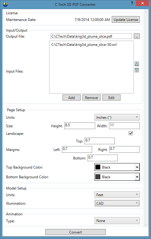
The following is a list of guidelines that must be considered when making EVS models that will be output as 3D PDF files using the *C Tech 3D PDF Conv
Guidelines for 3D Printing The following is a list of guidelines that must be considered when making visualizations that will be printed using 3D Systems (previously Zcorp) technology. As of this software release, no other full color 3D printer has been successfully tested with output from write vrml. You must follow the guidelines in write vrml in addition to these additional guidelines.
Subsections of write vrml
The following is a list of guidelines that must be considered when making EVS models that will be output as 3D PDF files using the C Tech 3D PDF Converter.
Note: The C Tech 3D PDF Converter is a separately purchased product not included with any other C Tech software licenses. Please see www.ctech.com for pricing.
EVS output from write_vrml. You must follow the guidelines in write_vrml in addition to these additional guidelines.
Let’s begin by building a simple application
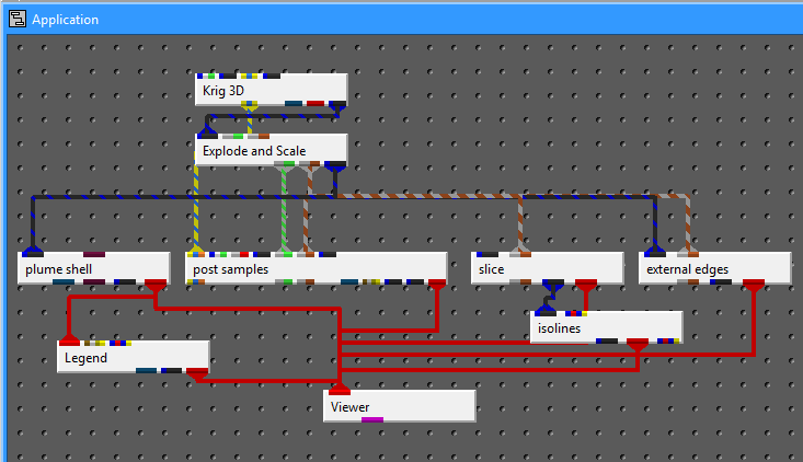
Whose output is:
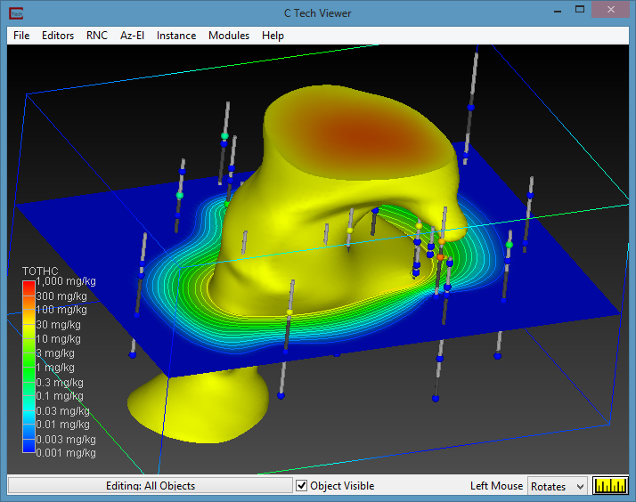
The first things we MUST do for VRML output are to remove the legend and use an Unlocked Background. If you see a gradient background in your viewer, you definitely aren’t using an unlocked background. Once you use an unlocked background, you can still set a solid (single) background color.
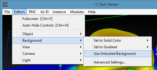
Always set your viewer to a Top View (180 Azimuth and 90 Inclination) before writing the VRML file.
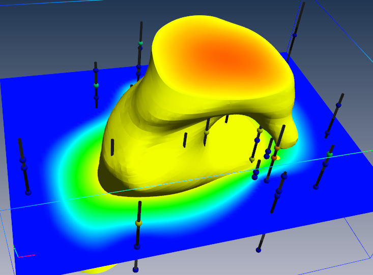
If we output this current model as VRML and convert to 3D PDF,
the results are less than wonderful:
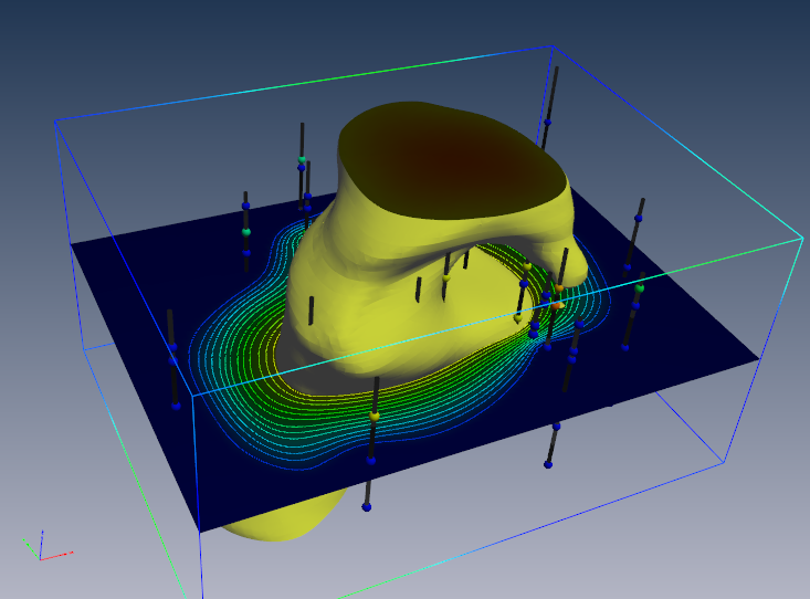
The above 3D PDF has three obvious problems:
- The top and bottom of the plume are very dark.
- The slice is dark
- post_sample’s borings are dark.
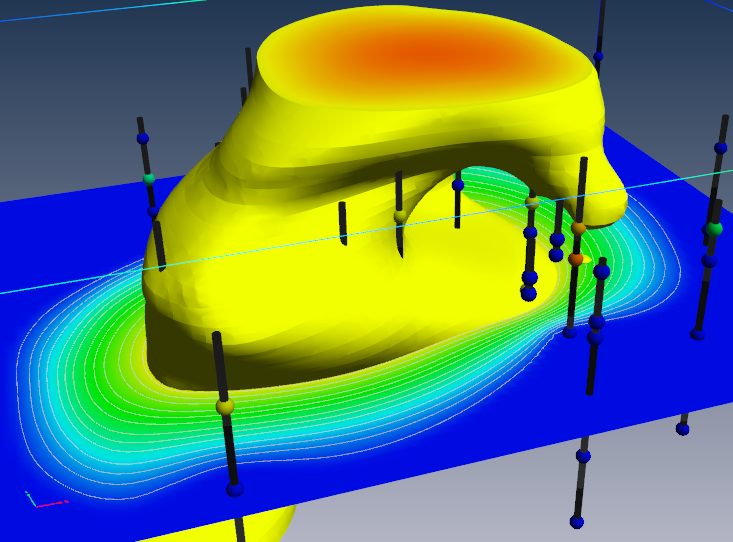
We need to modify the application using two texture_colors modules as follows:
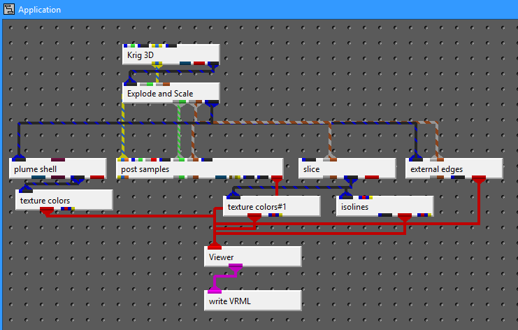
You’ll notice that in the revised application, the output in the viewer is virtually identical. This will address the first two problems, however we expect to resolve the dark borings in an upcoming release.
If we export this model to VRML and convert to PDF, the result is:
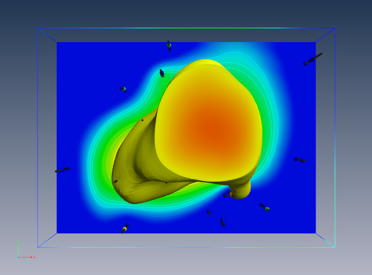
One other issue is that by default, we create isolines coincident with the surface(s) and resolve the coincidence in EVS using jitter. At some rotations you will notice that the isolines may disappear. This can be because jitter is not supported, but also because the underlying surface is so bright that the lines are not distinguishable.
This can be addressed using the surface_offset parameter in isolines. This will offset the lines from teh surface (in one direction) and eliminate the coincidence. However, this will also mean that the lines will not be visible from one side of the slice. Making the lines uncolored is another option.
Guidelines for 3D Printing
The following is a list of guidelines that must be considered when making visualizations that will be printed using 3D Systems (previously Zcorp) technology. As of this software release, no other full color 3D printer has been successfully tested with output from write vrml. You must follow the guidelines in write vrml in addition to these additional guidelines.
These guidelines are provided to minimize printing problems. Users should fully understand the issues below or they will likely not create VRML files suitable for 3D printing. Given the cost of the raw material it is best to do it right the first time!
Many of these issues (if not heeded) will be obvious when the model is viewed in Z Corp’s ZPrint software. Make sure the model is carefully examined in ZPrint before actual printing.
Internal Faces: You must avoid internal External faces. This naturally occurs when we cut a hexahedral volumetric model with our older plume module. The volumetric subset consists of hexahedron and tetrahedron cells. This creates surfaces that are internal to the model even though they represent the external faces of each set of cells. The real problem here is that the mating surfaces of each cell set are coincident (see 4 below). This major problem and many others are resolved by the intersection shell module.
Normals: Must have all surface normals facing outward to define a solid volume for printing (handled by intersection shell module)
Coincident surfaces: You CANNOT HAVE coincident surfaces. If two layers (or other objects) have coincident surfaces this will result in open parts and printing problems. You must separate the parts by a small amount (recommend 0.005 inches in final printed size) which should not be noticeable visually. Z-Print’s process will fuse these parts together (because there isn’t sufficient gap to keep them truly separate).
Overlapping parts: This is supported. It is possible to have two closed volumes overlap each other and Z-Print will sort it out so long as 1, 2 and 3 above are still valid.
Surfaces: Must be extruded or represented as a volumetric layer. Surfaces have no thickness and if placed coincident with the top of a volumetric object will result in leaving the volume OPEN (unclosed). This will cause serious problems.
Cell Data: Another limitation is the inability to mix nodal and cell data. Since we use nodal data for so many things you should always strip out the cell data and use nodal data exclusively. You must be aware of the following:
- Ensure that there are no modules connected to the viewer that contain cell data. The safest way to ensure this is to pass questionable modules through extract_mesh with “Remove Cell Data” toggle ON. Normally you would want the “Remove Nodal Data” toggle OFF.
- If you want your cell data (colors) to be displayed, pass the cell data through the cell data to node data module. However be aware that you’ll still need to use extract_mesh afterwards because cell data to node data doesn’t remove the cell_data it just creates new nodal data from cell data.
- Typical modules that have cell data are import vector gis, lithologic modeling, Solid_3D_Set, Solid_contour_set, and most of the modules in the Cell Data library.
Explode distance: Need to ensure that there is sufficient gap between exploded layers (separate parts) so that they don’t fuse together. Separation should be 1 mm (0.04 inches) minimum in the final print scale. Be aware that a 1 mm gap in the Z direction isn’t equivalent to a 1 mm separation if the mating parts have high slopes. If your mating surfaces have a 45 degree slope, the separation is reduced by cos(45) (~0.7). If you have higher slopes such as 80 degrees, the factor would be ~0.17. This would mean that you would need a Z gap of nearly 6 mm to ensure a 1 mm separation between parts.
Disconnected pieces: Although Z Print can print disconnected pieces, they won’t retain their spatial position. Plumes that aren’t connected to solid structure will just be loose pieces in the final print. This would also apply to post samples’ borings and spheres, unless they are connected by some common surface or geologic layer.
Concepts that are NOT Supported:
- Points and Lines: Points and Lines cannot be printed (except as elements of an image used in a texture map). Lines must be converted to some 3D solid structure (such as closed tubes) and they must be of sufficient thickness to have some strength AND must not be disconnected pieces. Points should be represented as glyphs of sufficient size and not be disconnected.
- Transparency: Transparency as an object property cannot be supported since Z Print’s ink is printed onto opaque plaster or starch powder. The illusion of transparency could be achieved by creating a texture map that was a blend (using the image transition module) between two different images.
- Volume rendering: This is a subset of Transparency and therefore is not supported at all.
- Jitter: First, you must make sure that coincident surfaces are avoided anyway. Jitter is designed into EVS to allow preferential visualization of coincident objects. With Z Printing we cannot have coincidence in the first place! Offset the desired primary object to ensure that it is visible. Remember no lines and no surfaces!
Thin sections: This is a somewhat subjective issue in that we really can’t tell you the definition of too fragile?. We would recommend a minimum thickness of 0.5 mm, but depending on the width (total cross sectional area of the section) this may be too fragile or exhibit too much distortion during curing. We still want to have lenses pinch out, but if sections get very thin, the pieces may break.
Top View: You should write out the VRML file from a top view If there are any truly flat (horizontal) surfaces, this keeps them flatter and smoother. Also, it helps to keep the models with the largest dimensions in the x-y plane (rather than z). This speeds up printing.