write evs field The write evs field module creates a file in one of several formats containing the mesh and nodal and/or cell data component information sent to the input port. This module is useful for writing the output of modules which manipulate or interpolate data (3d estimation , 2d estimation, etc.) so that the data will not need to be processed in the future.
export web scene connects via the vew port and writes all objects in your view as a 'C Tech Web Scene' (*.ctws), a single file which you and your cus
export pdf scene connects via the vew port and writes all objects in your view as a .evspdf file that C Tech's PDF Converter can convert to a 3D PDF.
This module will export the entire view (model) in the following formats to allow importing to other 3D modeling software:
export nodes export nodes provides a means to export an ASCII file containing the coordinates (and optionally the data) of any object in EVS. The output contains a header line and one row for each node in the input field. Each row contains the x, y, & z coordinates and optionally node number and nodal data.
export cad General Module Function export cad will output one or more individual objects (red port) or your complete model (purple input port from the viewer). Volumetric objects in EVS are converted to surface and line type objects. export cad preserves the colors of all cells and objects by assigning cell colors to each AutoCAD surface or line entity according to the following procedure:
export surface to raster The export surface to raster module will create a raster file in the GeoTiff format. It takes any input field, and writes a raster (in plan view) of the data provided from that field. Regions outside of the input area are masked with an appropriate NoData flag. A single data component (node or cell) can be exported to the GeoTiff file.
export vector gis The export vector gis module will create a file in one of the following vector formats: ESRI Shapefile (.shp); GMT ASCII Vectors (.gmt); and MapInfo TAB (*.tab). Although C Tech allows non-ASCII analyte names, ESRI does not. Please see this link on acceptable shapefile field (attribute) names. It basically says that only A-Z, a-z, 0-9 and “” are allowed. The only thing we can do when writing a shapefile is to change any unacceptable (non-ASCII) character to “” and add a number if there are more than one.
export horizon to raster export horizon to raster is used in conjunction with gridding and horizons with rectilinear grids of geologic data. A large number of formats are supported such as Surfer and ESRI grids. For some formats, each cell in your grid should be the same size. This will require you to adjust the extents of your grid and set the grid resolution according to:
write_lines The write_lines module is used to save a series of points with data connected by lines. These lines are stored in the EVS Line File format. Module Input Ports Input Field [Field] Accepts a field with or without data which represents lines
export horizons to vistas export horizons to vistas is used in conjunction with gridding and horizons. gridding and horizons can create finite difference grids based on your geologic data. It writes the fundamental geologic grid information to a file format that Ground Water Vistas can read. The output includes the x,y origin; rotation; and x-y resolutions in addition to descriptive header lines proceeded by a “#”.
Subsections of Export
write evs field
The write evs field module creates a file in one of several formats containing the mesh and nodal and/or cell data component information sent to the input port.
This module is useful for writing the output of modules which manipulate or interpolate data (3d estimation , 2d estimation, etc.) so that the data will not need to be processed in the future.
The saved and processed data can be read using read evs field, which is much faster than reprocessing the data.
Principal recommended format: EF2
The newest and strongly recommended format is EF2. This format is capable of containing additional field data and mesh types which are not supported in our Legacy format. Please note that this is the only LOSSLESS format for current and future EVS fields. Although the files created in EF2 format are generally larger than >EFBs, the further subsetting and/or processing of these updated fields can be dramatically more efficient.
- Uniform fields
- Geology (from gridding and horizons)
- Structured fields (such as irregular fields read in from Read_Field)
- Unstructured Cell Data (UCD format) general grids with nodal and/or cell data
- Special fields containing spheres (which are points with radii)
- Special fields containing color data (such as LIDAR data)
Legacy formats:
- The legacy formats below were the recommended formats in software releases before 2024. With our enhancements to EVS Fields, these formats must be considered LOSSY, meaning that some data and the (EF2) optimized grids will be compromised if these formats are use. We strongly recommend using theEF2 format.
- .eff ASCII format, best if you want to be able to open the file in an editor or print it. For a description of the .EFF file formats click here.
- .efz GNU Zip compressed ASCII, same as .eff but in a zip archive
- .efb binary compressed format, the smallest & fastest format due to its binary form
Module Input Ports
- Geologic legend Information [Geology legend] Accepts the geologic material information for the legend module.
- Input Field [Field] Accepts the field to be saved.
- File Notes [String / minor] Accepts a string to document the settings used to create the field.
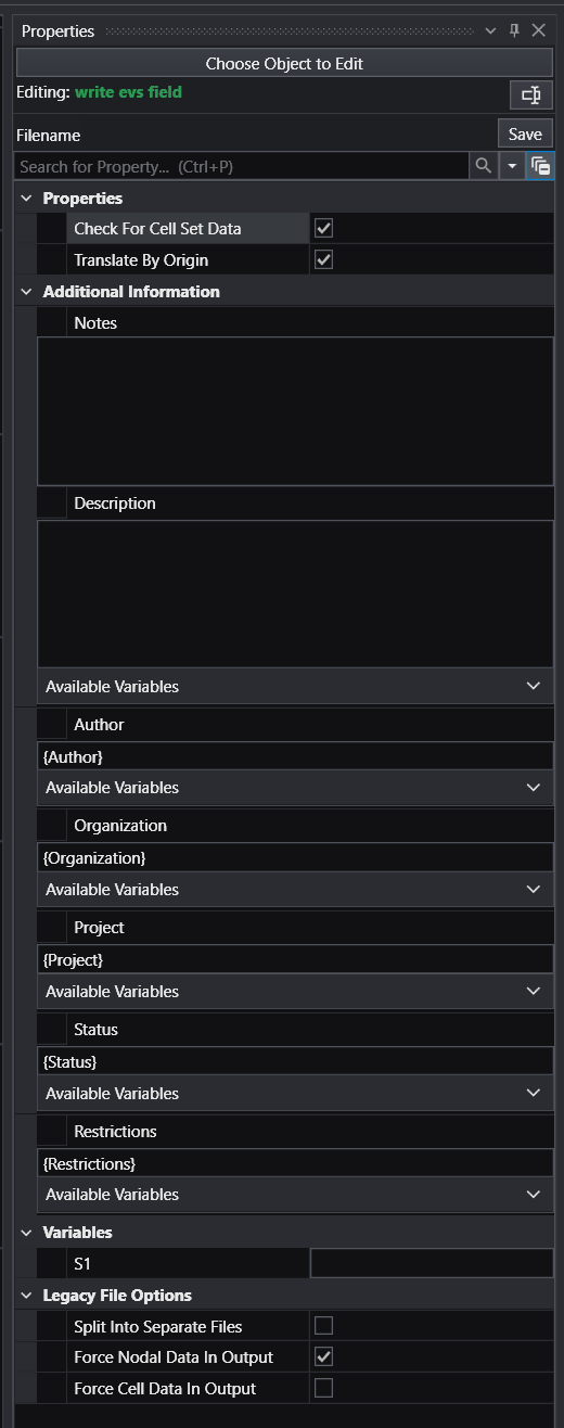
Module Parameters
There are only a few parameters in write evs field, but they provide important functionality and should be understood.
- Check for Cell Set Data (EF2 Only): Causes any cell data that is constant across a cell set to be saved as cell set data. This is more efficient and is recommended.
- Translate by (Application) Origin): Normally on, this should be turned off if the contents represent content which is not in your application origin. Examples are glyphs or inputs to modules such as cross section tubes
- LEGACY FILE OPTIONS
- Split Into Separate Files: This toggle applies only to EFF format files and makes it easier to create your own EFF files from similar data. It separates the header file (.eff) from the coordinates, data and connectivity.
- Force Nodal in Output: This toggle is on by default and ensures that fields without data are tagged as having data because many EVS modules may not allow connections for fields without data. It does not add data, it only tags the file as having data (even if it doesn’t)
- Force Cell in Output: Similar to the toggle above, but needed far less often.
export web scene connects via the vew port and writes all objects in your view as a “C Tech Web Scene” (*.ctws), a single file which you and your customers can load and view at: https://viewer.ctech.com/
Details on its use at How to Create C Tech Web Scenes.htm
WARNINGS:
- DATAMAPS ARE USED FOR PROBING: When using unlinked values (Min and Max) such that the resulting datamap is a subset of the true data range, probing in C Tech Web Scenes will only be able to report values within the truncated data range. Values outside that limited range will display the nearest value within the truncated range. This applies to the use of the Datamap parameters in post samplesor when the data range is truncated by clipping in the estimation modules or with the change min max module.
export pdf scene connects via the vew port and writes all objects in your view as a .evspdf file that C Tech’s PDF Converter can convert to a 3D PDF. This module requires a valid PDF Converter license in order to function.
This module will export the entire view (model) in the following formats to allow importing to other 3D modeling software:
- glTF 2.0 (.glb binary format)
- FBX (.fbx)
- COLLADA (.dae)
All files are written in a coordinates system where the X-Y origin (0,0) is the Application Origin. This is done to preserve precision in these formats which are fundamentally single precision.
export nodes
export nodes provides a means to export an ASCII file containing the coordinates (and optionally the data) of any object in EVS. The output contains a header line and one row for each node in the input field. Each row contains the x, y, & z coordinates and optionally node number and nodal data.
Module Input Ports
- Z Scale [Number] Accepts Z Scale (vertical exaggeration) from other modules
- Input Field [Field] Accepts a field with or without data
export cad
General Module Function
export cad will output one or more individual objects (red port) or your complete model (purple input port from the viewer). Volumetric objects in EVS are converted to surface and line type objects.
export cad preserves the colors of all cells and objects by assigning cell colors to each AutoCAD surface or line entity according to the following procedure:
a) If nodal data is present, the first nodal data component is averaged to the cells and that color is applied. This is equivalent to the appearance of surfaces in EVS with flat shading mode applied.
b) If no nodal data is present, but cell data is, that color is applied. This is equivalent to the appearance of surfaces in EVS with flat shading mode applied.
c) If neither nodal or cell data is present the object’s color is used.
The results should look fairly similar to the viewer in EVS except:
- AutoCAD has a very limited color palette with only 256 total colors. With some datamaps this limitation will be more problematic and it is possible that the nearest AutoCAD color may apply to multiple colors used in a subtle geology datamap.
- AutoCAD lacks of Gouraud shading support (as mentioned above) so all cells are flat shaded.
All “objects” in EVS are converted to separate layers based upon the EVS object name (as shown in the viewer’s Object_Selector).
Module Input Ports
- Z Scale [Number] Accepts Z Scale (vertical exaggeration) from other modules
- View [View] Connects to the viewer to receive all objects in the view
- Input Object [Renderable]: Receives inputs from one or more module’s red port
export surface to raster
The export surface to raster module will create a raster file in the GeoTiff format.
It takes any input field, and writes a raster (in plan view) of the data provided from that field. Regions outside of the input area are masked with an appropriate NoData flag. A single data component (node or cell) can be exported to the GeoTiff file.
Raster resolution can be controlled via the Grid Cell Size parameter, which will default (when linked) to a size which generates a raster of up to four million pixels, with fewer generated depending on how much the input shape deviates from having square extents.
When exporting certain cell data, such as Lithology, connecting the Geologic Legend Information port will allow the raster to include additional metadata in a raster dataset attribute table file. This additional file will allow programs such as ESRI’s ArcGIS Pro to automatically load the GeoTiff with proper names associated with each material.
Module Input Ports
- Input Field [Field] Accepts a field with data to export
- Geologic Legend Information Accepts the geologic information from an appropriate module, such as lithologic modeling, to associate data with names
export vector gis
The export vector gis module will create a file in one of the following vector formats: ESRI Shapefile (*.shp); GMT ASCII Vectors (*.gmt); and MapInfo TAB (*.tab).
Although C Tech allows non-ASCII analyte names, ESRI does not. Please see this link on acceptable shapefile field (attribute) names. It basically says that only A-Z, a-z, 0-9 and “_” are allowed. The only thing we can do when writing a shapefile is to change any unacceptable (non-ASCII) character to “_” and add a number if there are more than one.
If you plan to create a shapefile it will be better to change the analyte names to an ASCII equivalent that is more meaningful, but uses on the acceptable character set.
Info
Make sure to connect export vector gis after explode_and_scale to ensure that z-scaling is properly compensated.
Module Input Ports
- Z Scale [Number] Accepts Z Scale (vertical exaggeration) from other modules
- Input Field [Field] Accepts a field with or without data
export horizon to raster
export horizon to raster is used in conjunction with gridding and horizons with rectilinear grids of geologic data. A large number of formats are supported such as Surfer and ESRI grids. For some formats, each cell in your grid should be the same size. This will require you to adjust the extents of your grid and set the grid resolution according to:
Cell size = (Max:xy - Min:xy) / (grid-resolution -1)
NOTE: YOU MUST SELECT RECTILINEAR GRIDDING IN gridding and horizons
Module Input Ports
- Geology Export Output [Vistas Data] Accepts output from gridding and horizons for conversion to raster grids.
write_lines
The write_lines module is used to save a series of points with data connected by lines. These lines are stored in the EVS Line File format.
Module Input Ports
- Input Field [Field] Accepts a field with or without data which represents lines
export horizons to vistas
export horizons to vistas is used in conjunction with gridding and horizons. gridding and horizons can create finite difference grids based on your geologic data.
It writes the fundamental geologic grid information to a file format that Ground Water Vistas can read.
The output includes the x,y origin; rotation; and x-y resolutions in addition to descriptive header lines proceeded by a “#”.
Module Input Ports
- Geology Export Output [Vistas Data] Accepts output from gridding and horizons for conversion to Groundwater Vistas format