GEO: Borehole Geology Stratigraphy
Geology data files basically contain horizontal and vertical coordinates, which describe the geometry of geologic features of the region being modeled. The files must be in ASCII format and can be delimited by commas, spaces, or tabs. Borehole Geology files must have a .geo suffix to be selected in the file browsers of EVS modules. The z values in .geo files can represent either elevation or depth, although elevation is generally the easiest to work with. When chemistry or property data is to be utilized along with geologic data for a 3-D visualization, a consistent coordinate system must be used in both sets of data.
Geology files should also specify the geologic layer material (color) number and layer names. This provides a mechanism to color multiple (not necessarily adjacent) layers as the same material.
Borehole Geology files (.geo suffix) must have the same number of entries for each boring location, so that every geologic layer in the system is represented in each boring. However, EVS allows flags to be included in the .geo files to allow automated processing of data in systems where geologic layers are not present in all locations (i.e., the layers “pinch out”). Also, EVS accommodates borings that were not extended deep enough to encounter layers that the scientist knows are present in the system. The use of these flags greatly facilitates the production of .geo data files, and minimizes the amount of manual interpretation the scientist must do before using EVS to analyze, understand, and refine a geologic model. For layers that pinch out, a flag of pinch can be used for automated estimation of the “depth” to the bottom of that layer. Entering this flag is essentially equivalent to entering the bottom depth of the layer directly above the pinched out layer (which is also an acceptable way to prepare the file). When EVS encounters this flag in a file, it assigns the pinched out layer a zero thickness at this location. For borings that do not extend to the depths of geologic layers in the system, a flag of short is included in the file for all layers below the depth of the boring. Including this flag notifies EVS to ignore the presence of this boring when kriging the surface of the layers below the total depth of the boring.
Format:
The file name must have a .geo suffix to be selected in the module’s file browser. The format below is the same for all EVS modules which read geology files:
You may insert comment lines in .geo files.
- Comment lines must begin with a ’#’ as the first character of a line.
The first non-commented line of the file is the header line (line 1 described below).
Line 1: Any header message: Except that:
- $W or $G as the first two characters signifies a special geology file which contains unrelated surfaces such as historical water tables. These flags turn off checking for corrupt geology file formats (situations where lower surfaces are above higher surfaces) and automatically turn off kriging in thickness space.
- Line one cannot be BLANK
Line 2: Elevation/Depth Specifier:
- The only REQUIRED item on this line in the Elevation or Depth Specifier.
- This line should contain the word Elevation or Depth (case insensitive) to denote whether sample elevations are true elevation or depth below ground surface.
- If set to Depth all surface descriptions for layer bottoms are entered as depths relative to the top surface. This is a common means of collecting sample coordinates for borings.
- Note that the flags such as pinch or short are not modified.
- This line should contain the word Elevation or Depth (case insensitive) to denote whether sample elevations are true elevation or depth below ground surface.
- Line 2 SHOULD contain names for each geologic surface (and therefore the layers created by them).
- There are some rules that must be observed.
- The number of surface (layer) names MUST be equal to the number of surfaces. Therefore, if naming layers, the first name should correspond to the top surface and each subsequent name will refer to the surface that defines the bottom of that layer.
- A name containing a space MUST be enclosed in quotation marks example (“Silty Sand”). Names should be limited to upper and lower case letters, numerals, hyphen “-” and underscore “_”. The names defined on line two will appear as the cell set name in the explode_and_scale or select cell sets modules. Names should be separated with spaces, commas or tabs.
- There are some rules that must be observed.
- Line 2: After the names, include the units of your coordinates (e.g. feet or meters). It must follow the names for each material number.
Line 3: The first integer (n) is the number of lines to follow. The second integer (m) is the number of geologic layer depths plus one (for the top surface). The 3rd and subsequent numbers are the colors for each surface in your model. Layers are colored by the color of the surface that defines their bottoms. The first two color numbers should be the same (top and bottom of the first layer).
When used with fence_geology, the order of the borings determines the connectivity of the fence diagram and must match the chemistry file for krig_fence.
Note that X and Y corresponding to Eastings and Northings are used. Be careful not to reverse these.
Line 4: First line of sample data. X, Y, top surface, and “m” depths or elevations to the bottom of each geologic layer. Coordinates, elevations (depths) and boring name can be separated by one comma and/or any number of spaces or tabs.
Two different flag parameters are included to accommodate special conditions. These flags are
A: Boring terminates early or surface information is missing. This flag class is used to identify that a boring did not continue deep enough to find the bottom of a geologic layer, OR that a section of a core sample is missing (lost, damaged, etc.) and that no determination of the location of this surface can be made from this boring. This is distinctly different than a surface (layer) that is not present because it has been determined that it has pinched out. The flags that are used for this class are [note: all flags are case insensitive, but spelling is critical]:
- missing
- unknown
- unk
- na
- short
- terminated
- term
In the sample file below, BOR-24 was not deep enough to reach to the bottom of the Lsand (lower sand) layer or the gravel layer. Rather than use the bottom of the boring (a meaningless number), the short flag is used so that this boring will not be used to determine the bottom of these two layers. Similarly BOR-72 is not deep enough to be used in determining the bottom of the last (Gravel) layer. The flags that are used for this class are [note: all flags are case insensitive, but spelling is critical]:
B: This flag class is used to identify that a geologic layer is not present because it has pinched out for this particular boring. It can be “thought of” as numerically equivalent to using the value one column to the left. However, now that gridding and horizons includes special treatment for the pinchflag, using the value to the left is not strictly equivalent.
- pinch
- pinched
- pinch-out
Note that several layers pinch out in borings WEL-67, BOR-23, BOR-70 and BOR-24, so the pinch flag was used for these layer’s entries instead of any numerical value.
IMPORTANT: There are two important things to consider when using the flags above:
- It is wholly inappropriate to have a pinch follow a short. Pinch denotes that the layer above is zero thickness. It is equivalent to using the numeric value to the left. However if it were to follow a short (unknown) it would be meaningless since the short is interpreted to be missing information.
- If your last defined surface has fewer than 3 numeric values (with all the rest being missing/short), it will be poorly defined since it takes 3 points to define a plane. If there are no numeric valuesthe surfacecannot be created.
…
Line 3+n is the last line of the file.
AN EXAMPLE FILE FOLLOWS:
| X | Y | TOP | BOT_1 | BOT_2 | BOT_3 | BOT_4 | BOT_5 | BOT_6 | BOT_7 | Boring |
|---|---|---|---|---|---|---|---|---|---|---|
| Depth | Top | Fill | SiltySand | Clay | Sand | Silt | Sand | Gravel | feet | |
| 7 | 8 | 5 | 5 | 3 | 1 | 4 | 2 | 4 | 6 | |
| 11856.7 | 12764.0 | 0 | 5.0 | 18.2 | 23.5 | pinch | pinch | 69.0 | 105.0 | WEL-67 |
| 11889.6 | 12772.2 | 0 | 1.5 | 17.0 | 22.0 | pinch | pinch | 63.0 | 105.0 | BOR-23 |
| 11939.1 | 12758.4 | 0 | 2.5 | 16.0 | 25.5 | pinch | pinch | 63.0 | 105.0 | BOR-70 |
| 12002.8 | 12759.8 | 0 | 1.0 | 17.0 | 27.0 | pinch | 47.0 | short | short | BOR-24 |
| 12085.1 | 12749.0 | 0 | 1.0 | 17.5 | 25.7 | 45.7 | pinch | 68.0 | 105.0 | WEL-71 |
| 12146.7 | 12713.2 | 0 | 1.0 | 18.0 | 26.5 | 32.5 | 39.5 | 65.0 | short | BOR-72 |
| 12199.7 | 12709.8 | 0 | 1.0 | 16.5 | 22.5 | 27.5 | 35.5 | 70.0 | 105.0 | WEL-12 |
This file has 7 boreholes with 8 entries (surfaces) per borehole, corresponding to the top surface and the bottom depths of 7 geologic layers. Note that the fourth and sixth layers are both designated to be material 4. This allows you to easily create layers with the same material the same color.
Other Examples of Geologic Input Files
Example of a .geo file for sedimentary layers and lenses (containing pinchouts)
Example of a .geo file for Dipping Strata Geologic_File_Example_Outcrop_of_Dipping_Strata
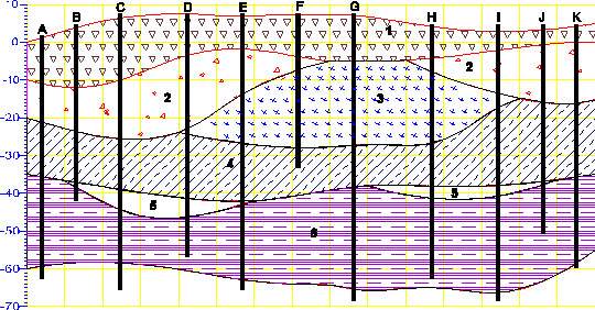
Geologic File Example: Sedimentary Layers and Lenses
Geologic File Example: Sedimentary Layers & Lenses Both example files below represent valid forms for the geology file associated with the above figure. For file 1, line 2 of the file is “1”, therefore all surface elevations are entered as actual elevations relative to a fixed reference such as sea level (not depths) and the relationship between x, y, and elevation must be a right handed coordinate system. Note that X and Y corresponding to Eastings and Northings are used. Be careful not to reverse these.
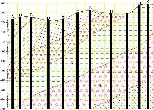
Geologic File Example: Outcrop of Dipping Strata
Geologic File Example: Outcrop of Dipping Strata EVS is not limited to sedimentary layers or lenses. The figure below shows a cross-section through an outcrop of dipping geologic strata. EVS easily model the layers truncating on the top ground surface. The file below represents the geology file associated with the above figure. Line 2 of the file is “Elevation”, therefore all surface elevations are entered as elevations (not depths) and the relationship between x, y, and elevation must be a right handed coordinate system. The pinch flag is used extensively to identify that a geologic layer is not present (pinched out) for a particular boring. It is equivalent to using the value one column to the left. The file was created with the assumption that there was no desire to model any layers below -70 foot elevation and that all borings extend to/beyond that depth.
Geology Files for Production of a Fence Diagram
Geology Files for Production of a Fence Diagram Discussion of Geology Files for Fence Sections Files used to create fence diagrams contain only those borings that the user wishes to include on an individual cross section of the fence, in the order that they will be connected along the section. The resulting set of files includes one .geo file for each cross section that will be included in a fence diagram. The order of the boring listings determines the connectivity of the fence diagram, and must match the order of the borings in the associated chemistry file when chemistry is to be displayed on the diagram. The data for the boring(s) at which individual sections will be joined to produce the fence diagram are included in each of the cross section files that will intersect. Generally, it is easiest to create the geology file for the complete 3-D dataset, and then cut and paste the individual section files from the complete file. Examples of a 3-D geology file and a typical set of fence diagram files are presented below.